
 Language
 English
 русский
 Deutsch
 عربى
 Tiếng Việt
 Türk
 ไทย
 italiano

High Precision Vertical Machining Center
-
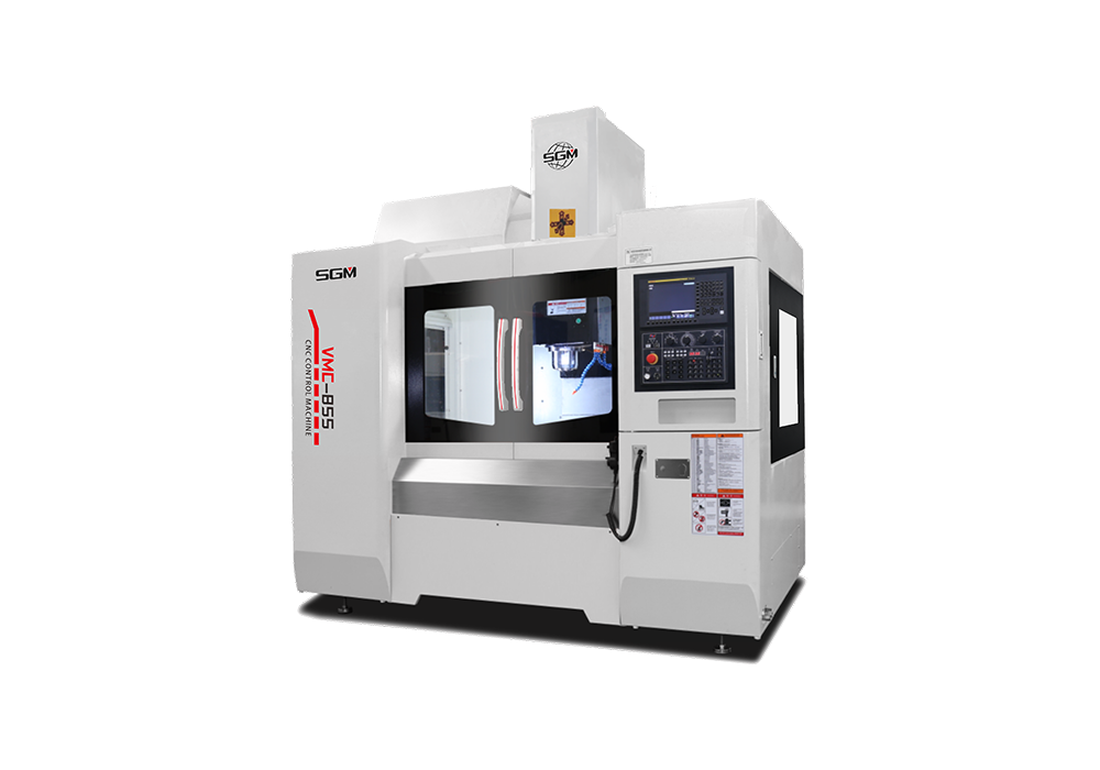 VMC-855
 High Speed Vertical Machining Center
-
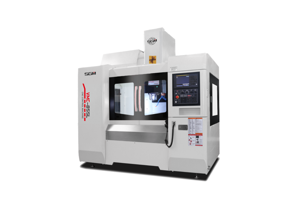 VMC-855L
 Heavy Duty Vertical Machining Center
-
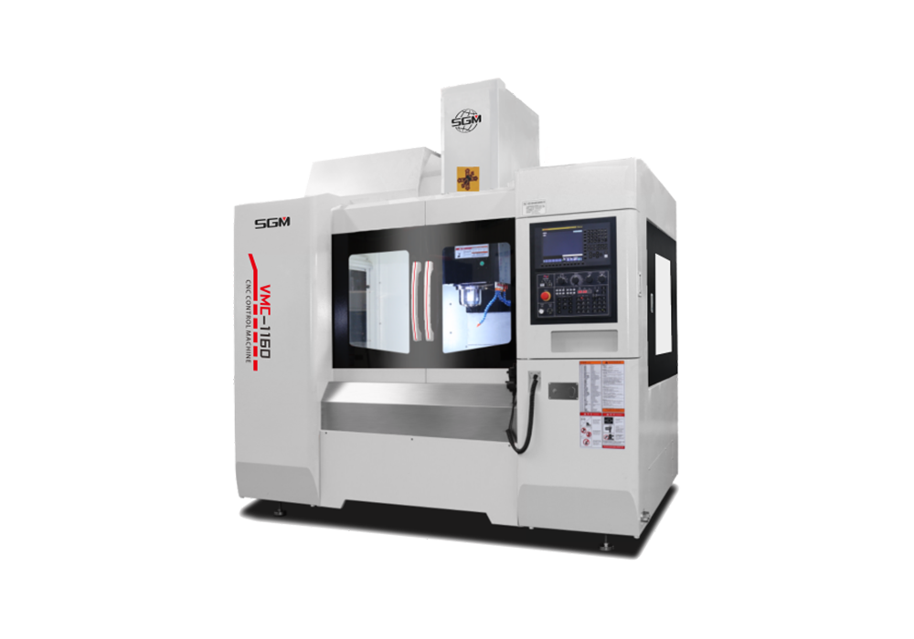 VMC-1160
 High-Accuracy Vertical Machining Center
-
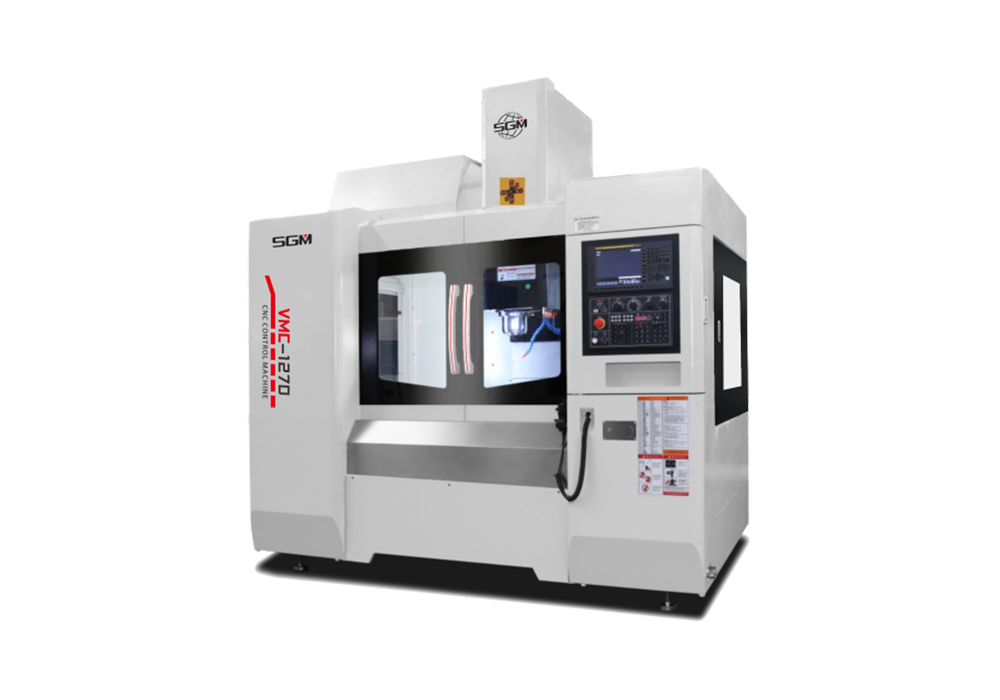 VMC-1270
 High Spindle Speed Vertical Machining Center
-
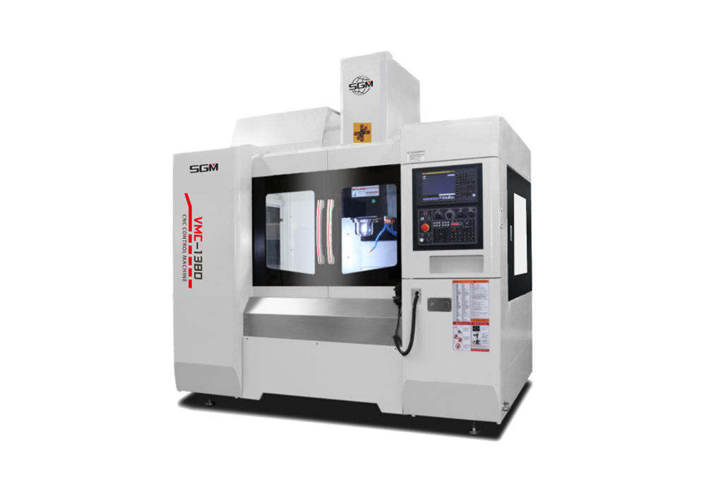 VMC-1380
 High Feed Vertical Machining Center
-
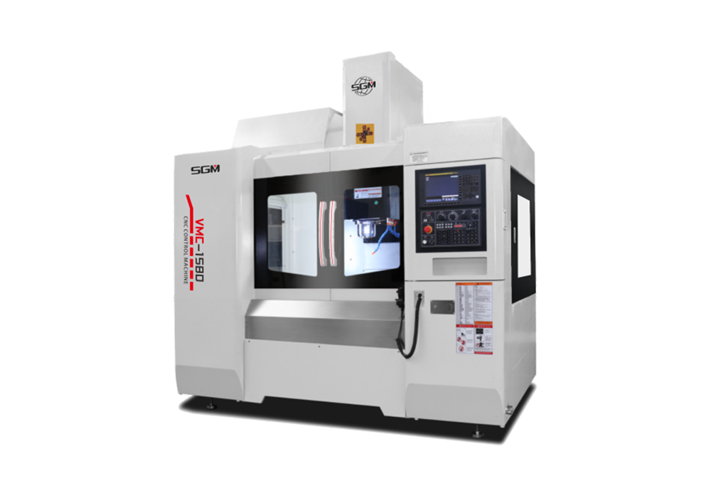 VMC-1580
 High Load Ultra Wide Table Vertical Machining Center
Vertical machining centers are the core Class 1 product category of our CNC equipment. Classified as 3-axis / multi-axis vertical CNC milling machines with vertically oriented spindles, they support composite machining processes including precision metal milling, drilling, boring, tapping, chamfering and curved surface forming.
They cater to machining fields covering mold manufacturing, automotive components, 3C precision parts and general mechanical fittings, capable of both mass production and single-piece precision machining. Our product portfolio includes three major tiers: mid-to-high-end, high-precision and high-speed 5-axis models. Benchmarked against precision standards of top-tier German and Japanese imported machine tools, all complete machines comply with China’s national standards for machine tool safety and precision.
All models have obtained EU CE certification to meet export requirements for EU markets.
SGM is the core brand of Stuttgart CNC Equipment (Anhui) Co., Ltd. As the original manufacturing base for the SGM brand, Stuttgart is a specialized high-end equipment manufacturer dedicated to the R&D, design and production of CNC gantry, vertical and horizontal machining centers. The vertical machining center manufacturer & supplier brings together top-tier technical talents and builds a well-structured professional talent pipeline, focusing on the R&D and iteration of a full portfolio of high-end CNC equipment. Its precision vertical machining center products are widely applied in high-end manufacturing sectors including automotive, mold making, shipbuilding and medical devices.
Certificates and Honours
-
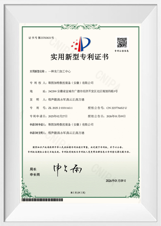 Utility Model Patent Certificate‑Gantry Machining Center
-
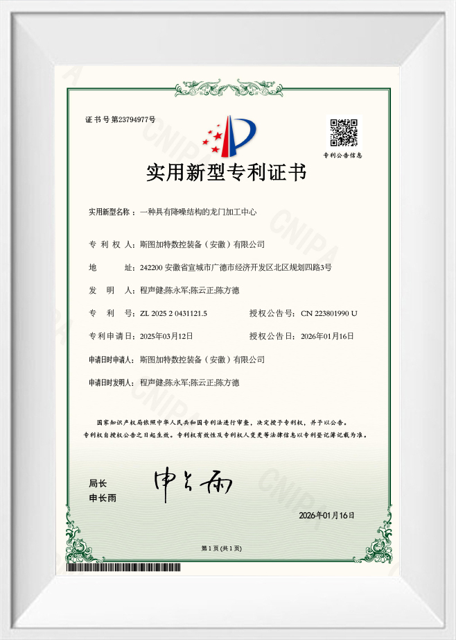 Utility Model Patent Certificate‑Gantry Machining Center With Noise‑Reduction Structure
-
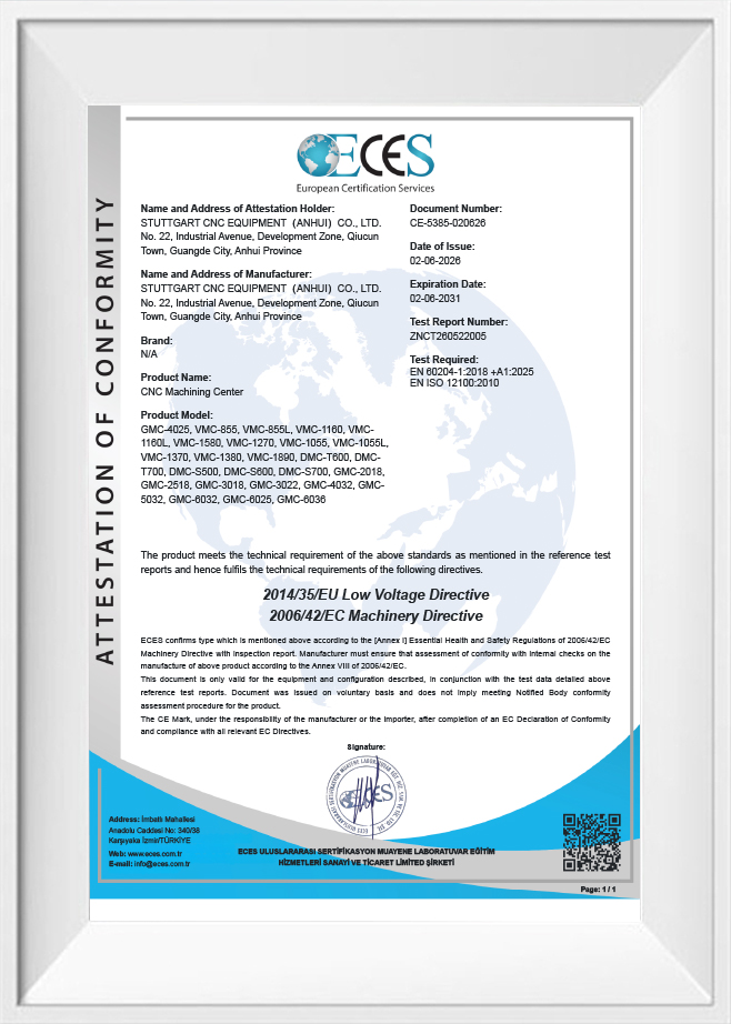 CE certification
Vertical Machining Center: Working Principles, Applications, and Selection Guide
Complex metal parts often need several operations, tight consistency, and steady production. A vertical machining center (VMC) meets those needs with a vertically oriented spindle that carries out milling, drilling, tapping, boring, and other operations from a program. Depending on configuration, one setup may cover several of these steps, so the part gets handled less often. This guide covers how a VMC runs, which materials it cuts, where it's used, and which specifications deserve a close look.
What Is a Vertical Machining Center and How Does It Work?
A VMC is a CNC machine whose spindle axis sits vertically over the worktable. The cutter turns in the spindle while the controller moves the tool and part along a programmed path.

VMCs are common for flat faces, pockets, slots, holes, and contoured features in metal. Many models include an automatic tool changer (ATC), which lets the machine swap cutters partway through a program.
How Does a Vertical Machining Center Work?
A typical job runs through these stages:
- Workpiece preparation: The part is located and clamped with a fixture or other suitable workholding.
- Program setup: The CNC program sets coordinates, toolpaths, spindle speeds, feed rates, and the order of operations.
- Tool selection: The operator loads tools by hand, or the ATC picks them, depending on the machine.
- Machining: The spindle spins the cutter while the control moves the axes to remove material.
- Tool changes and further operations: On equipped machines, the VMC moves between milling, drilling, tapping, and boring without operator intervention.
- Inspection: The finished part is measured against the drawing for dimensions, hole locations, surface condition, and other requirements.
The sequence varies with part geometry, material, tooling, program, and machine setup.
What Are the Main Components of a Vertical Machining Center?
A VMC combines mechanical structure, motion control, cutting tools, and support systems:
| Component | Main Function |
| CNC Control System | Reads the program and directs machine motion |
| Spindle | Turns the cutter at the required speed |
| Bed and Column | Carry the structure and contribute to rigidity |
| Worktable | Holds the part and fixture during cutting |
| Feed Drive and Guideway System | Moves the machine along each axis |
| Automatic Tool Changer (ATC) | Swaps tools automatically on equipped machines |
| Coolant System | Supplies coolant or cutting fluid when the process needs it |
| Chip Removal System | Clears chips from the cutting zone |
Designs differ between models. Spindle characteristics, guideway design, tool magazine capacity, and chip handling should all be matched to the work you plan to do.
What Do the X, Y, and Z Axes Do?
On a conventional three-axis VMC, the three linear axes control the basic motion:
- X-axis: Horizontal travel, left to right.
- Y-axis: Horizontal travel, front to back.
- Z-axis: Vertical travel relative to the spindle and table.
Some machines move the table, others move the spindle head, and some do both. Rotary axes add more orientations for the part. A rotary axis on its own doesn't mean the machine can cut with several axes moving at once, because the control and configuration also have to support that.
What Machining Operations Can a VMC Perform?
A VMC handles several kinds of material removal, as long as the machine, tooling, and workholding are suited to the job:
| Operation | Purpose | Typical Use |
| Face Milling | Produces a flat surface | Part faces and reference surfaces |
| End Milling | Removes material with the cutter's end and sides | Pockets, steps, and profiles |
| Slot Milling | Cuts slots or grooves | Keyways, channels, and features |
| Drilling | Creates holes | Mounting and fastening holes |
| Tapping | Cuts internal threads | Threaded connections |
| Boring | Enlarges or corrects existing holes | Holes that need a specific diameter |
| Reaming | Refines hole size and finish | Holes finished to tight specifications |
| Contour Machining | Follows a programmed path to form a profile or surface | Molds, dies, and shaped parts |
What a given machine can do depends on its spindle, tool interfaces, control functions, work envelope, and other configuration details.
What Is the Difference Between a CNC Milling Machine and a Vertical Machining Center?
"CNC milling machine" is a broad label for computer-controlled milling equipment. A VMC is one specific type, defined by its vertical spindle and, in its usual form, its ability to run several operations and tools in one program.
The categories overlap, because some CNC mills also have ATCs and advanced controls. Compare the machines by their actual features, not the name on the nameplate.
| Feature | CNC Milling Machine | Vertical Machining Center |
| General Definition | Broad category of CNC milling equipment | CNC machine with a vertical spindle |
| Tool Changing | Manual or automatic, depending on the machine | Often fitted with an ATC |
| Machining Operations | Set by machine design and tooling | Commonly combines milling, drilling, tapping, and more |
| Production Workflow | Varies by machine type | Supports programmed multi-operation work |
| Configuration Range | Wide range of structures and capabilities | Available in various sizes, axis setups, and automation levels |
What Are the Applications and Advantages of a Vertical Machining Center?
VMCs suit work that demands controlled material removal, accurately placed features, and repeatable results. Whether a particular machine fits depends on the part's geometry, material, dimensional requirements, and configuration.
Which Materials Can a Vertical Machining Center Process?
A VMC can cut a wide range of metals, provided the spindle, tooling, workholding, and parameters match the material:
| Material | Key Machining Considerations | Typical Parts |
| Aluminum Alloys | Tool geometry, cutting speed, chip evacuation, surface finish | Housings, brackets, frames, structural parts |
| Carbon Steel | Grade, cutting load, spindle torque, tool choice | Machine parts, support plates, mechanical components |
| Stainless Steel | Heat control, cutting parameters, tool wear, lubrication | Equipment fittings, housings, precision parts |
| Cast Iron | Hardness, abrasiveness, tooling, chip management | Machine bases, housings, structural parts |
| Copper | Ductility, tool geometry, chip control | Electrical and conductive parts |
| Brass | Grade, cutting conditions, tool geometry | Fittings, connectors, machined hardware |
| Other Engineering Materials | Cutting conditions specific to the material and machine | Parts for specialized industrial needs |
Check material compatibility against the exact grade, hardness, part dimensions, and operations. A machine that handles aluminum easily may need a stiffer structure or a different spindle to cut heavy steel.
Which Industries Use Vertical Machining Centers?
- Automotive parts: VMCs produce brackets, housings, and mounting plates that need accurately located holes, milled faces, or threads. The method depends on the drawing, material, and volume.
- Mold and die making: Mold bases, cavities, and inserts often require pocket milling, contouring, drilling, and finishing. Geometry, surface requirements, tool access, and tolerances set the capability you need.
- General machinery: Plates, supports, fixtures, and machine housings often combine flat faces, slots, holes, and threaded connections in one workflow.
- Electronics and electrical equipment: Metal enclosures, mounting parts, connector housings, and equipment frames may need precisely placed holes and machined surfaces. Fixture design and dimensional control matter when parts must align during assembly.
- Industrial equipment: Machinery components vary widely in material and size. Part dimensions, cutting loads, and feature count help determine the right configuration.
What Are the Practical Advantages of a Vertical Machining Center?
A VMC pays off when its capabilities match your process:
- Multi-operation machining: A suitable configuration can run milling, drilling, tapping, and other operations in one setup.
- Program-controlled movement: CNC programming defines toolpaths and sequences in a repeatable way.
- Repeatable positioning: Consistent workholding, good machine condition, and reliable program execution help hold dimensions across runs.
- Automated tool changing: An ATC switches between compatible tools without an operator stopping the cycle.
- Flexibility: Different tools, fixtures, and programs let one machine handle a range of geometries.
- Process integration: Several operations can share one workflow, which can cut handling and setup time.
These are possibilities, not promises. Cycle time, dimensional results, and consistency depend on the machine, material, tooling, operator practice, and cutting conditions.
What Is the Difference Between 3-Axis, 4-Axis, and 5-Axis Vertical Machining Centers?
Axis configuration determines how the tool and part can move relative to each other. The right choice depends on how many faces need machining, how the features are oriented, the geometry, and the tolerances.
| Configuration | Basic Capability | Typical Applications | Key Considerations |
| 3-Axis VMC | Linear motion along X, Y, and Z | Plates, brackets, pockets, and holes reachable from one main direction | Part orientation, fixture design, feature access |
| 4-Axis VMC | Three linear axes plus one rotary axis | Parts that need rotation or machining on several sides | Rotary capacity, fixture clearance, positioning needs |
| 5-Axis VMC | Three linear axes plus two rotary axes | Complex contours, angled faces, and multi-directional access | Kinematics, programming, tool clearance, control capability |
A 3-axis machine is often enough when features can be reached from one direction. A 4-axis setup presents more faces to the cutter, and a 5-axis setup handles more complex angles.
Indexing and simultaneous machining differ. An indexed rotary axis repositions the part between cuts. Simultaneous multi-axis machining requires the machine and control to move several axes together during the cut.
Extra axes don't automatically improve accuracy or shorten cycle times. Let the geometry, fixturing, programming, and production process drive the decision.
How to Choose a High Precision Vertical Machining Center?
Picking a high-precision VMC means looking at the entire machining process. Part size, material, spindle performance, axis travel, positioning, tooling, and workflow together decide whether a machine suits your work.
How Should Workpiece Size and Axis Travel Be Evaluated?
Axis travel sets how far the machine can move. Compare it with part dimensions, fixture size, tool length, and the positions you need to reach.
Before choosing a VMC, pin down:
- Maximum part length, width, height, and weight
- Required X, Y, and Z travel
- Fixture height and clearance for the spindle and tool
- Reach needed to access every feature
- Room for loading, unloading, and tool movement
A part can fit on the nominal table and still cause trouble if the fixture, tool holder, or target features create clearance problems. Check the whole setup envelope, not just the part's outline.
How Do Spindle Speed, Power, and Torque Affect Machine Selection?
The spindle drives the cutter, and its characteristics limit which operations the machine can handle.
- Speed determines how fast the tool turns. Different materials, cutter diameters, and operations need different speed ranges.
- Power describes the energy the spindle can deliver under specified conditions.
- Torque matters when an operation needs strong rotational force, such as certain tools, materials, or deep cuts.
Evaluate speed, power, torque, tooling, and cutting load together. A high top speed doesn't prove that a machine can handle heavy cutting or a particular material.
How Should Machining Accuracy and Repeatability Be Evaluated?
Positioning accuracy and repeatability describe different things:
- Positioning accuracy is how closely the machine reaches a commanded position under defined test conditions.
- Repeatability is how consistently it returns to the same position when the move is repeated under similar conditions.
Both matter when parts have tight dimensions or several related features. Key influences include:
- Structural and mechanical rigidity
- Axis drive and guideway characteristics
- Spindle condition and thermal behavior
- Tool wear and toolholding stability
- Workpiece clamping and fixture repeatability
- Calibration, maintenance, and the operating environment
- Machining parameters and inspection methods
Read the published accuracy figures together with the conditions behind them. A positioning spec doesn't guarantee the dimensions of every finished part, because the cutting process, material, temperature, tooling, and measurement method all shape the result.
What Should Be Checked in the Tool Changer and CNC Control System?
The tool changer and control should match your workflow. Check:
- Magazine capacity: Enough positions for the tools you need.
- Tool dimensions and weight: Permitted diameter, length, and weight compared with your tooling.
- Tool-change compatibility: The toolholding interface and supported change method.
- Programming functions: Support for the cycles, coordinate handling, and axis movements your parts require.
- Programming workflow: How programs are written, transferred, verified, and maintained.
- Future needs: Whether planned operations will call for extra tooling or functions.
Equipment varies by model, so confirm these details in the documentation for the machine you're considering.
Why Do Machine Rigidity, Cooling, and Chip Removal Matter?
Rigidity helps the structure resist cutting forces and vibration, which affects stability, dimensional consistency, tool wear, and surface quality.
Coolant manages heat and lubrication, and good chip evacuation keeps chips from interfering with the tool or part. When you assess these systems, consider:
- The materials and operations involved
- Expected chip shape and volume
- Depth and geometry of pockets and holes
- Coolant needs of the selected tools
- Access to the work area for cleaning and maintenance
- How cutting forces affect the machine and fixture
Deep pockets and hard-to-clear chips call for a different setup than shallow milling and simple hole patterns.
How Can Production Requirements Guide VMC Selection?
| Production Requirement | Key Evaluation Factors |
| Aluminum components | Speed range, tooling, chip evacuation, surface finish |
| Steel mechanical parts | Spindle torque, rigidity, tooling, cutting parameters |
| Parts with many holes | Axis positioning, drilling capability, workholding, program control |
| Mold and die work | Contouring capability, tool access, finishing, programming functions |
| Parts machined on several sides | Fixture arrangement, rotary-axis needs, access to each face |
| Tight tolerances | Published accuracy, repeatability, thermal stability, inspection methods |
| Multiple operations | Magazine capacity, tool-change compatibility, program sequencing |
| Large or heavy parts | Axis travel, table size, allowable load, fixture clearance |
Use this table to narrow your options before comparing specific models. Make the final decision with the drawings, the process plan, the required tolerances, and the manufacturer's confirmed specifications.
Why Consider SGM CNC Vertical Machining Centers?
SGM CNC offers a dedicated Vertical Machining Center category for buyers comparing CNC equipment. Begin with your part's machining requirements, then check the specifications of the model you're considering.
When reviewing the information, focus on:
- Application fit: Does the documented capability match your material, part size, and operations?
- Configuration: Spindle characteristics, axis travel, table size, tool-change arrangement, and control functions.
- Precision: How the published accuracy compares with your dimensional and repeatability needs.
- Workflow: How tooling, workholding, coolant, and chip removal fit your process.
- Technical discussion: Bring representative drawings and requirements so the conversation stays specific.
These points give you a sound basis for judging both the machine and the supplier. Confirm specific capabilities against the technical data for the relevant SGM CNC model rather than assuming them from the category name.
For more detail, visit the SGM CNC Vertical Machining Center product page to review the equipment and identify the specifications that matter for your parts.
When you evaluate a high-precision VMC, define your operations and tolerances first, then compare the specifications and configurations that bear on them. If SGM CNC equipment is on your list, review its Vertical Machining Center information and confirm model-specific capabilities against your actual parts.

- No.22, Industrial Avenue, Qiucun Town, Guangde City, Xuancheng City, Anhui Province, P.R.China
- +86-13185627261
- stgtcnc@163.com
Copyright © SGM Rights Reserved.
 Vertical Machining Center for Sale