
 Language
 English
 русский
 Deutsch
 عربى
 Tiếng Việt
 Türk
 ไทย
 italiano

CNC Engraving and Milling Machine
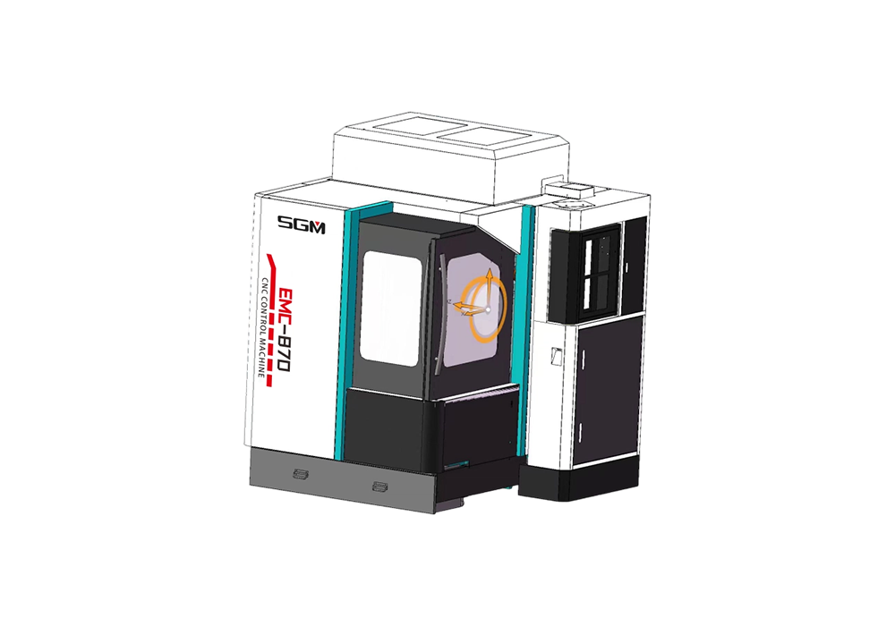
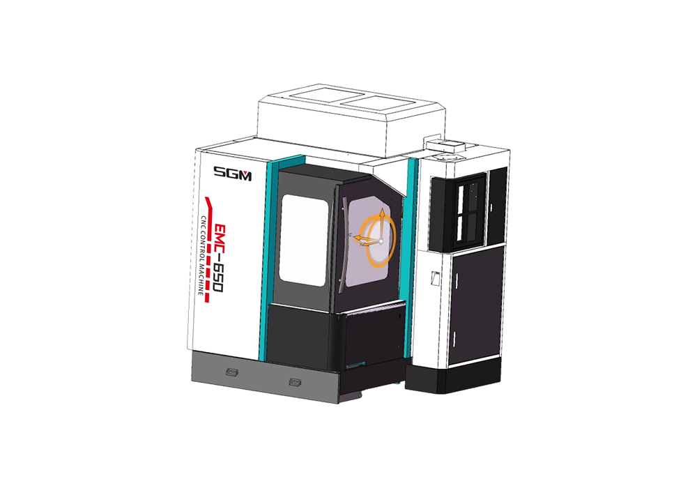
CNC engraving and milling machines are the core Class 1 product category dedicated to precision mold machining of our brand. They adopt an integrated small gantry cross-slide structure equipped with high-speed motor spindles, supporting composite machining processes including high-speed engraving, fine milling, shallow cavity roughing, drilling and tapping.
Optimized for high-gloss finish machining of small & medium precision molds, relief carvings, electrodes and miniature precision special-shaped parts, they differ from vertical machining centers built for heavy cutting and drilling tapping centers specialized only in drilling and tapping operations. This series targets processing scenarios demanding ultra-high spindle speed, superior contour accuracy and smooth delicate surface textures.
The machines are ideal for low-volume high-precision production in mold workshops, precision hardware factories, cultural creative engraving factories and 3C electrode manufacturing.
All models have obtained EU CE certification to meet export requirements for EU markets.
SGM is the core brand of Stuttgart CNC Equipment (Anhui) Co., Ltd. As the original manufacturing base for the SGM brand, Stuttgart is a specialized high-end equipment manufacturer dedicated to the R&D, design and production of CNC gantry, vertical and horizontal machining centers. The CNC engraving machine manufacturer brings together top-tier technical talents and builds a well-structured professional talent pipeline, focusing on the R&D and iteration of a full portfolio of high-end CNC equipment. Its CNC engraving tool products are widely applied in high-end manufacturing sectors including automotive, mold making, shipbuilding and medical devices.
Certificates and Honours
-
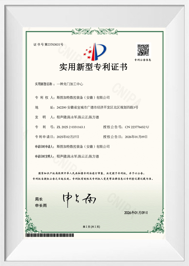 Utility Model Patent Certificate‑Gantry Machining Center
-
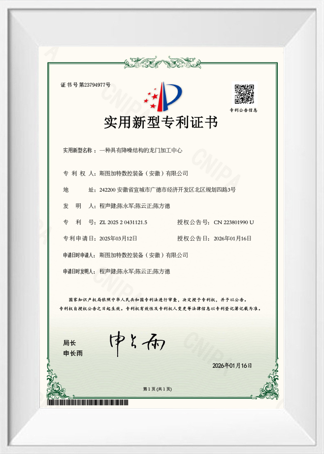 Utility Model Patent Certificate‑Gantry Machining Center With Noise‑Reduction Structure
-
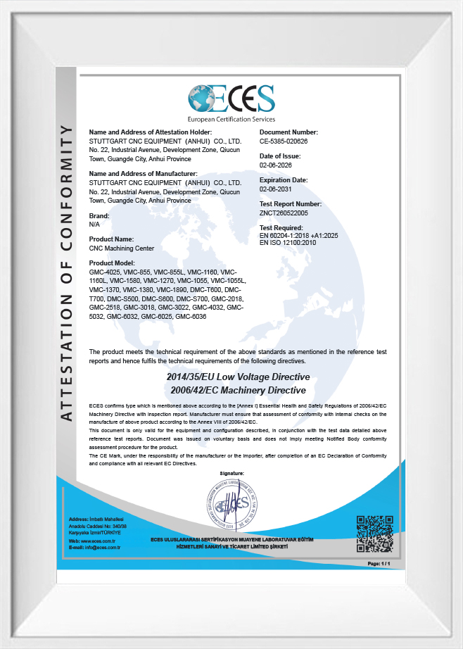 CE certification
CNC Engraving and Milling Machine: Working Principles, Materials, and Selection Guide
Good-looking parts rarely come from a simple cut. Crisp lettering, detailed contours, accurate pockets, and an even surface finish all depend on how the machine structure, cutting tools, programming, and process control work together. A CNC engraving and milling machine pairs computer-controlled motion with rotating cutters to carry out these operations.
What Is a CNC Engraving and Milling Machine?
A CNC engraving and milling machine is a computer numerical control tool that removes material from a workpiece along programmed paths. It can engrave, contour, slot, pocket, and mill, as long as its structure, spindle, tooling, and control system support the job.
Manual machining depends on the operator's hand at every step. CNC machining follows programmed coordinates and cutting instructions, so the machine can repeat complex shapes and fine patterns with consistent tool movement.
How Does a CNC Engraving and Milling Machine Work?
The process follows a digital workflow that turns a design into a finished part:
- CAD design: A 2D drawing, vector file, or 3D model defines the geometry, dimensions, and features.
- CAM programming: Software generates toolpaths based on the design, the cutting tools, the material, and the machining strategy.
- Workpiece setup: The material is secured to the table with clamps, a vise, or a dedicated fixture.
- Machine configuration: The operator installs the cutter, sets the work coordinates, checks clearances, and enters spindle and feed parameters.
- CNC machining: The controller runs the program, coordinating spindle rotation and axis movement to remove material along the toolpath.
- Inspection: The finished part is checked for dimensions, engraving depth, surface condition, and other drawing requirements.
The final accuracy depends on the whole process, not the program alone. Tool selection, workholding stability, machine calibration, thermal conditions, and cutting parameters all shape the result.
What Are the Main Components of a CNC Engraving and Milling Machine?
Several subsystems work together to control cutting movement and hold the geometry you need:
- Frame and bed: Support the machine and resist cutting forces. Rigidity keeps vibration and dimensional drift under control.
- Spindle: Rotates the cutter. Its speed, power, torque, and runout determine which materials and operations it can handle.
- Tool holder and collet: Hold the cutter in the spindle. Secure retention and concentricity are essential for consistent results.
- Worktable and fixtures: Hold the workpiece steady during engraving and milling.
- Linear guides and transmission: Guide and drive each axis. Depending on the design, this can include linear guideways, ball screws, rack drives, or other motion parts.
- CNC controller and drives: Interpret the program and control axis movement, spindle commands, and related functions.
- Cooling and chip removal: Manage heat and clear chips when the material and process call for it.
Configurations vary by model. A machine built mainly for fine engraving will differ in spindle character and structure from one designed for heavy metal milling.
What Is the Difference Between CNC Engraving and CNC Milling?
Both processes use controlled cutters to remove material, but they differ in purpose, feature size, cutting strategy, and the material removal they require.
| Comparison Factor | CNC Engraving | CNC Milling |
| Primary Objective | Text, symbols, fine lines, and detailed patterns | Surfaces, slots, pockets, contours, and component geometry |
| Typical Tools | Engraving cutters, V-bits, and small-diameter end mills | End mills, face mills, ball-nose cutters, and other milling tools |
| Cutting Strategy | Follows fine contours with light engagement | Uses roughing and finishing passes based on the geometry |
| Material Removal | Usually limited, especially for shallow details | Can range from shallow finishing cuts to substantial removal |
| Key Performance Factors | Detail resolution, tool runout, depth control, and edge quality | Rigidity, cutting forces, dimensional accuracy, chip evacuation, and surface finish |
| Common Uses | Nameplates, lettering, markings, and decorative patterns | Housings, fixtures, pockets, mold features, and machined components |
The two categories overlap. One machine can handle detailed engraving and milling if its capabilities suit both. Cut depth isn't the only deciding factor. Material, cutter geometry, machine rigidity, and toolpath strategy all determine the right approach.
What Materials and Applications Suit CNC Engraving and Milling Machines?
These machines can process many metals and non-metals, as long as the equipment and tooling suit the job. Material compatibility should be judged together with part size, tolerances, surface finish requirements, and cutting forces.
Which Materials Can a CNC Engraving and Milling Machine Process?
The table below lists common examples. Actual compatibility depends on the machine, spindle, tooling, and required depth.
| Material | Typical Applications | Key Considerations |
| Aluminum Alloys | Housings, panels, brackets, precision parts, and mold features | Chip evacuation, tool engagement, and built-up edge on cutters |
| Copper | Electrical components, conductive parts, and detailed profiles | Tool geometry and cutting parameters that control adhesion and heat |
| Brass | Instrument parts, decorative plates, and engraved labels | Burr formation and surface finish |
| Mild Steel | Fixtures, industrial components, and selected machined features | Machine rigidity, spindle capability, tooling, and cutting forces |
| Stainless Steel | Corrosion-resistant parts and selected precision features | Work hardening, heat generation, tool wear, and coolant needs |
| Engineering Plastics | Housings, prototypes, insulating parts, and precision plastic components | Heat-related melting, deformation, and dimensional change |
| Acrylic and Other Suitable Plastics | Panels, displays, lettering, and decorative components | Cutter and feed choices that reduce edge melting and surface damage |
Wood and composites can also be machined on suitably configured equipment. Dust extraction, tooling, and workholding requirements differ from metal work.
Harder metals and heavy milling need extra attention to spindle torque, frame rigidity, cutter strength, tool overhang, and chip removal. A machine built for light engraving shouldn't be assumed capable of cutting steel.
What Machining Operations Can These Machines Perform?
Depending on the design and tooling, these machines support several common operations:
- Surface engraving: Lettering, symbols, serial numbers, and decorative patterns on suitable surfaces.
- Contour milling: Follows programmed outlines for external profiles and internal shapes.
- Slot milling: Produces grooves and channels sized by the cutter and toolpath.
- Pocket milling: Removes material within defined areas to create recesses.
- Face milling: Machines surfaces to flatness and finish targets within the machine's capability.
- Drilling: Creates holes when the spindle, tooling, positioning, and workholding are suitable.
- Three-dimensional contouring: Uses suitable cutters and toolpaths for curved surfaces, reliefs, and complex profiles.
Some machines can complete several operations in one setup. That cuts down on re-clamping and helps keep features in the right position relative to each other. Still, the available operations depend on axis configuration, tool access, work envelope, and control functions.
Which Industries Use CNC Engraving and Milling Machines?
These machines are used wherever controlled material removal and detailed geometry matter:
- Precision components and mechanical parts: Slots, mounting features, pockets, and contours in suitable metal parts. Dimensional requirements depend on the drawing and the full process.
- Electronics and electrical components: Panels, housings, insulating parts, and selected conductive components. These often demand tight control of dimensions, surface condition, and material properties.
- Mold and tooling: Machines with adequate rigidity, spindle power, and travel can produce mold features, electrodes, fixtures, and tooling components. Hardened or complex materials may call for specialized equipment and extra finishing.
- Industrial labels and nameplates: Engraving produces text, symbols, and identifiers on compatible materials. Readability depends on feature size, cutter geometry, material, and depth.
- Product development and prototyping: Digital designs become physical prototypes and functional parts, which supports dimensional checks and design refinement.
For any of these, check the machine against your actual workpiece and process. An industry match alone doesn't prove that a model can achieve the required geometry, tolerance, or production rate.
How to Choose a High Precision CNC Engraving and Milling Machine?
Choosing a high-precision CNC milling machine means matching the workpiece and process to the machine's structure, spindle, motion system, and inspection capability. A high spindle speed or a single headline accuracy figure says little about whether a machine will deliver precision on your parts.
Start with the results you need, then work through the specifications that determine whether the machine can produce them.
Which Technical Parameters Matter Most?
The following parameters give you a practical framework.
- Spindle Speed, Power, and Torque
Spindle speed sets how fast the cutter turns. Power and torque determine how much cutting load the spindle can handle. Small engraving cutters often need high speeds, while larger tools and metal milling need torque at suitable speeds.
The right combination depends on the material, cutter diameter, tool geometry, cutting speed, and feed rate. High speed doesn't make a machine suited to heavy milling, and high power doesn't guarantee fine engraving quality. - Axis Travel and Working Area
X, Y, and Z travel define how far the tool and workpiece can move. The usable area also depends on fixture size, tool length, workpiece height, and clearance.
Compare machines using your largest part, the deepest cut, and the room needed to clamp the material. A large work envelope only helps if the machine maintains performance across all of it. - Positioning Accuracy and Repeatability
Positioning accuracy is how closely an axis reaches a commanded point. Repeatability is how consistently it returns to a point under the same conditions.
These differ. A machine can repeat a move very consistently while still carrying a systematic error. Calibration, compensation, axis alignment, transmission quality, and test conditions all affect the numbers.
Keep in mind that machine specifications don't equal finished-part accuracy. Workpiece deformation, thermal expansion, tool wear, cutting forces, fixturing, and machining strategy also shape the final dimensions. - Machine Rigidity and Thermal Stability
Rigidity keeps the machine from deflecting under cutting forces. Weak structures lead to vibration, chatter, poor finish, and dimensional drift, especially in metal.
Temperature changes affect the machine, the spindle, the tools, and the workpiece. For demanding work, the shop environment, warm-up routine, maintenance condition, and thermal compensation all matter. - CNC Control System and Motion Components
The controller coordinates programmed motion and commands. Drive motors, linear guides, and ball screws determine how that motion is produced and controlled.
When you assess a machine, look at programming compatibility, coordinate functions, interpolation capability, the control interface, and whether it can run the toolpaths your application needs. Judge motion systems by the accuracy, speed, and load you require, not by component names alone. - Tooling, Cooling, and Chip Removal
Tools must suit the material, the feature geometry, the finish requirement, and the spindle interface. Runout, tool length, cutter wear, and holder condition all affect accuracy and surface quality.
Cooling needs vary. Some materials and operations benefit from cutting fluid, while others run well with air-assisted chip clearing. Good chip evacuation prevents recutting, surface damage, and premature tool wear.
How Should Machine Accuracy and Machining Performance Be Evaluated?
Evaluate precision with measurable criteria tied to the finished part:
| Evaluation Item | What to Check | Why It Matters |
| Positioning Accuracy | Published specifications and measurement conditions | Shows how closely commanded positions are reached |
| Repeatability | Test conditions and repeated positioning results | Shows consistency across repeated moves |
| Spindle Runout | Measurement at the tool or spindle interface | Affects cutting stability, tool wear, and feature quality |
| Surface Finish | Required finish and measured sample results | Indicates whether extra finishing is needed |
| Dimensional Accuracy | Measurements against the drawing | Confirms the part meets its dimensional requirements |
| Structural Stability | Construction and performance under realistic cutting loads | Identifies vibration and deformation risks |
| Process Consistency | Results from repeated machining under defined conditions | Shows whether output stays within required characteristics |
When you evaluate a high-precision CNC milling machine, ask for the relevant specifications and, where possible, sample machining results or documented test procedures. Before comparing figures across machines, confirm the measurement method, test conditions, workpiece material, tool setup, and inspection equipment. Numbers measured under different conditions aren't directly comparable.
A sample part is especially useful for small engraved features, narrow slots, fine surface details, or tight tolerances. It tests the proposed process against your real requirements rather than general claims.

- No.22, Industrial Avenue, Qiucun Town, Guangde City, Xuancheng City, Anhui Province, P.R.China
- +86-13185627261
- stgtcnc@163.com
Copyright © SGM Rights Reserved.
 High Precision CNC Milling Machine